


Restoring a 2005
Fender Hot Rod Deluxe
What twenty years of heat, vibration and previous repairs can do to one of Fender’s most successful valve amplifiers
A familiar amplifier, now twenty years old
The Fender Hot Rod Deluxe hardly needs an introduction. Since the series appeared in the 1990s, the 40-watt 1×12 combo has become a familiar sight in rehearsal rooms, studios, pubs, clubs and backlines. It is loud, practical, comparatively affordable and capable of a very usable clean sound.
The other side of that success is that a great many original-generation examples are now around twenty years old. They have lived through thousands of heating and cooling cycles, speaker vibration, valve changes, transport and, in many cases, a few repairs.
This 2005 example was bought specifically as an unhurried workshop project. It arrived in working order and in unusually good cosmetic condition. The aim was to document what could be found in a typical Hot Rod Deluxe, correct the age-related weaknesses properly, establish its measured performance before and after the work, modify some tone characteristics, and turn it into a really reliable demonstration of what these amps can become.

A good-looking survivor
From the front the cabinet and grille cloth had survived extremely well. There were no major tears or obvious signs of abuse. It was, however, a bit grubby.
Closer examination told a little more of its history. Small blooms of mould were present on the rear covering, with light oxidation elsewhere. Together they suggested that the amplifier had probably spent some time in a slightly damp environment.
The amplifier as received

Some mildew on the rear panel indicates the amp may have been stored somewhere damp

Oxidation on the hardware, and much of the lettering has been scratched off, making it even herder to read
Initial internal inspection
Removing the rear panel revealed an interior that was surprisingly clean for its age. There was mild surface oxidation and evidence that a small amount of liquid had at some point run down the left-hand side of the chassis near the mains cable entry and transformer mounting, but there was no sign of serious water damage.

Mostly original - but not untouched
The amplifier still contained the usual IC-brand electrolytic capacitors in most positions. Three high-voltage filter capacitors had been changed previously, with reasonable quality components.
The valve complement consisted of three Fender-branded Sovtek 12AX7 preamp valves and a pair of Russian Sovtek 5881WXT output valves.
Testing the valves before changing anything
Before soldering work began, the existing valves were tested so that their condition could be assessed independently of the later service work. Replacing parts first and testing valves afterwards makes it much harder to distinguish the condition in which the amplifier actually arrived.

The complete valve set before servicing: two Sovtek 5881WXT output valves and three Fender-branded Sovtek 12AX7s.

One of the output valves under test on the mighty Hickok 600A
An exceptionally close output pair
Both Sovtek 5881WXT output valves measured exactly 11,250 µmhos on my beloved calibrated 1953 Hickok mutual-conductance tester. By this measurement the pair was exceptionally closely matched.
The three Fender-branded Sovtek 12AX7 preamp valves measured between 1,050 and 1,160 µmhos. There was therefore nothing in the valve-test results to suggest an obviously weak or badly mismatched valve set.
Establishing a before-service baseline
After checking the fitted T1.6A mains fuse was correct, the amplifier was then powered and assessed before dismantling - on the current-limiter first to make sure there were no dramatic faults, and then the mains supply was set to exactly 240V so that the figures would be meaningful when compared with the final test. In standby it drew 210 mA; switched on, 336mA - nothing unexpected here.
The amplifier passed audio and both channels worked. The reverb and channel switching were functional and the controls were not especially noisy, although several felt rather stiff.
There were, however, several clues that all was not well. Background hum was higher than I would accept, there was more hiss than desirable and the amplifier occasionally produced moderately loud random clicks. None of the controls affected the hum. More significantly, gently pressing the main PCB with an insulated tool could make the hum change or disappear. That strongly suggested a mechanically intermittent connection somewhere on the board.
At around 230 Hz a separate raspy buzz or rattle became apparent around the loudspeaker. Touching the speaker basket changed it. That symptom was recorded rather than chased immediately; with a full mechanical inspection still to come, there was little point spending time diagnosing something that might simply turn out to be loose hardware.
The final baseline measurement was maximum clean output. Into an 8 Ω dummy load the amplifier delivered 42 V peak-to-peak at the onset of clipping. That is about 14.85 V RMS, or 27.6 watts - appreciably short of the nominal 40-watt rating.
Dismantling & some mechanical faults
Once the initial tests were complete, the chassis could come out. Before concentrating on the electronics I checked the loudspeaker and baffle fixings, something I routinely do on combo amplifiers.
Every baffle retaining nut was loose by roughly one turn. The loudspeaker mounting screws were considerably worse: one required around five complete turns before it was properly tight. Given that touching the speaker basket had changed the 230 Hz rattle during the initial test, this immediately provided a plausible mechanical explanation - although it would still need to be checked again after reassembly.
With the chassis out, scattered corrosion was visible around the switches and valve-socket area. It was not severe, but this is why it's a bad idea to store your amp in the garage.

In Fairly original condition - only the 22uf 500V filter caps have been replaced....

....but not to a high standard - we'll see why this "topside" method can cause problems
The previous capacitor repair
The replacement high-voltage capacitors had looked as though they had been fitted from the component side without removing the PCB. Once the board was removed and the capacitors taken out, that suspicion was confirmed.
The original capacitor leads had been cut above the PCB and bent into hooks. The replacement capacitor leads had then been hooked around those remnants and soldered in place. It's called "J-hooking" and was how your grandad used to get his radio fixed. It is an understandable shortcut on an amplifier whose main PCB is inconvenient to remove, but crucially, you can't see what has happened to the original solder joint beneath the board (your grandad's radio probably didn't have a PCB, so this wasn't a problem). In this case, the solder had liquified and flowed away from the joint. There was barely any solder remaining at the terminal pad. Whatever electrical contact remained was not something I would regard as reliable. It also provided a very plausible explanation for the earlier observation that flexing the PCB changed the hum.

With the solder removed, the mechanical J-hook splice in all it's dubious glory

You can't see this unless the board is removed!
Cracked valve-socket joints
The capacitor joint was not the only significant finding on the solder side. Every pin on both octal output-valve sockets showed cracked solder joints. In several cases a complete circular fracture could be seen around the socket pin.

Many heating and cooling cycles eventually causes the solder joints to crack

All the old solder is removed, and the joints are re-soldered to a high standard
Overheating Pads & Traces:
The board also showed the familiar heat discolouration around the low-voltage supply dropper resistors and around the resistor associated with the footswitch supply. Looking from the solder side confirmed that the thermal stress extended through the board. The tracks and pads were still intact, but the area had spent a long time running hot.

Discolouration around the low-voltage dropper resistors and Zenner diodes

Left to "cook" for much longer, and this heat will damage the pads and traces
Service, reliability upgrades and tone mods.
All of the electrolytic capacitors were removed and replaced, including the earlier high-voltage replacements. The old J-hook repairs were eliminated so that the new capacitors were connected directly to properly remade PCB joints. The cracked output-valve socket joints were resoldered.
The low-voltage dropper resistors and their associated diodes were renewed. The replacement resistors were mounted clear of the PCB to reduce direct heat transfer into the board. The heat-stressed footswitch supply resistor was also addressed. The remainder of the PCB, including controls, jack sockets and other mechanically stressed connections, was inspected; nothing comparable to the output-socket cracking was found.
The pots and switches were serviced before reassembly. The controls, which had felt somewhat stiff during the initial assessment, were cleaned and lubricated with DeoxIT F5.
Tone
Surrey Audio Work's tried and tested tone modifications were then completed, including replacing two control pots, three capacitors and two resistors, which all help to bring the circuit back towards a more traditional Fender spec.

Resistors and diodes raised up for better heat dissipation, and to keep them away from the board

So that's the board work complete
A new control-panel overlay
There was also a cosmetic part to the project. The original control-panel graphics were tired, and I couldn't find one in Europe, so I designed my own replacement vinyl overlay, from measurements taken from the chassis. The finished panel was printed as a satin/matte black vinyl with white graphics, retaining the familiar Fender-style layout while replacing the damaged original surface.
This turned into a small project in its own right: pot and jack centres had to be measured accurately, the numeral arcs and labels refined, and the artwork adjusted so that the controls lined up correctly. The final print was not bad at all - the fit is within roughly half a millimetre, and it's a massive improvement on what was there, and will be much easier to see than white on polished chrome, on a well lit stage.
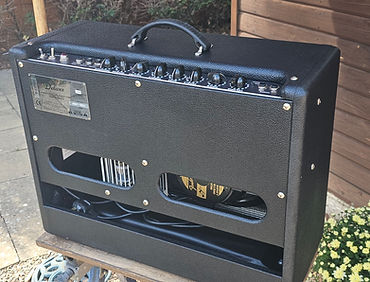
After cleaning the Tolex thoroughly it's looking quite smart

I would make the numerals smaller next time, but it's so much better than before

With the PCB already out, the overlay could be aligned and fitted while access was easy.
The exercise also produced a practical solution for a common issue on these older hotrod amplifiers - so I have stock!
And of course I had to buy loads of them!
240 V rewire and controlled power-up
These Hotrod amplifiers always come wired for 230 V primary connection. The transformer also provides a 240 V tapping, so during reassembly the primary wiring was changed to suit the 240 V mains supply more normally encountered in the UK.
The rebuilt chassis was then connected to the dummy load, oscilloscope and bias probes and powered through the current limiter. With 100 W of incandescent lamp in series, the behaviour was normal, with no sign of excessive current draw. Once there was confidence that the rebuilt amplifier was behaving normally, the limiter was removed and the supply set to 240 V. Plate voltage on the output pair was around 430-432 V before the final bias adjustment.
Biasing the Sovtek 5881WXT pair
The Sovtek 5881WXT sits in an awkward part of valve folklore because different references and users assign rather different plate-dissipation figures to it. Rather than biasing on an optimistic 30 W assumption, I chose to treat these valves as 25 W devices. That provides a sensible compromise: not unnecessarily cold if the valve is capable of more, but not unduly stressful if its realistic continuous rating is closer to the lower figures sometimes quoted.
My usual target here is around 55% of maximum plate dissipation. After adjustment the bias probes showed approximately 31 mA and 33 mA, with plate voltages of 427 V and 429 V respectively. The B+ during the final operating measurements settled around 405 V. Once the output pair was biased correctly, the operating conditions were measured, recorded and compared to previous Hotrod Deluxes, to ensure everything was correct and as expected.


Wouldn't be without my Eurotubes Probes!
5881WXT treated as 25 W • target approximately 55% plate dissipation

Standard Surrey Audio Works Report Sheet
Output Power Increase
The most striking before-and-after measurement was the clean output power. Before servicing, the amplifier had clipped at around 42 V peak-to-peak into 8 Ω - about 28 W. After the recap and reliability work, it reached 49.5 V peak-to-peak before visible clipping.
49.5 V peak-to-peak Into an 8 Ω load, that is about 38.3 W: essentially back where a nominal 40-watt Hot Rod Deluxe ought to be.
The obvious candidate for the recovered full-load performance is therefore the power supply. Ageing electrolytic capacitors can appear ok at idle yet struggle to maintain the DC rails when the amplifier is asked to deliver substantial output power.
Noise, clicks - and the stubborn 230 Hz buzz
The electrical noise performance was now much better. Residual hum measured about 8 mV peak-to-peak at the output and hiss roughly 1.5 mV. The small amount of hiss remaining was entirely acceptable.
More importantly, the random clicks and pops heard before the service had disappeared.
The mechanical noise around 230 Hz was reduced after tightening the previously loose baffle and speaker hardware, but it had not completely gone. This time the source could be localised more precisely. Pressing the baffle from the front in a particular place, stopped the rasp. Sliding a filling knife between the recessed baffle and cabinet also stopped it.
Hot Rod Deluxe baffles are only supported at the top and bottom, leaving the side edge to resonate. A thin strip of medium-density black packing foam was pushed into the gap with the filling knife.
As the foam was being inserted, the character and level of the 230 Hz tone changed noticeably before the raspy vibration disappeared altogether.

Neutrik is one of the only plugs where the solder bucket is the same piece of metal as the mating terminal = no rivets to vibrate loose.
Speaker-connection reliability improvement
Before final assembly I replaced the stock moulded speaker jack plug with a new Neutrik angled plug. The speaker wires were soldered to the terminals for additional reliability rather than relying on crimp connections, which can loosen with vibration or eventually work-harden and fracture.
While removing the original crimp connector, the aluminium rivet securing the small terminal board to the speaker basket broke. The board was refitted using a stainless-steel screw and lock washer.
Giving it a listen
Before the long soak test, I plugged a guitar in and spent around half an hour simply playing the amplifier. T Measurements are not a substitute for listening to a guitar amplifier as a musical instrument after all.
I've refurbed and modded many Hotrod Deluxes now, and the results are genuinely impressive. The clean channel sounds substantially better than a stock Hot Rod Deluxe I am used to hearing. As an engineer I'm not that comfortable with such adjectives, but I'd say "sparkling, but with a depth and openness that is reminiscent of classic vintage Fenders. I genuinely found that it made the strings on my workshop Samick Squire Strat sound as though they were not as old as they really are (I must change them soon)!

Thermal checks and extended soak test
The completed amplifier was then run into a dummy load for an extended sweep-tone soak test. The sweep covers the whole frequency spectrum the amp is capable of, and the power output is set at 70% of max Thermal images were taken during sustained operation, concentrating on the renewed low-voltage dropper area and the output valves.
As you can see - these resistors get hot, as do the Zenner diodes next to them - getting them raised off the board is a must.
Electrical safety testing
Once the amplifier was fully reassembled it received a PAT test.
I also make a point of checking earth continuity at the sleeve of an input jack. On a guitar amplifier this is an important accessible conductive point: the player is effectively connected to the amplifier chassis through the guitar lead, so it is not enough simply to establish continuity at an arbitrary chassis switch.

Is your tech qualified to complete PAT tests?
In Conclusion.....
This amplifier arrived working and looking better than many examples of the same age, but detailed inspection uncovered a surprisingly long list of developing problems: ageing electrolytic capacitors, a dubious previous repair causing a hum issue, cracked solder around every pin of both output-valve sockets, thermally stressed supply components, loose speaker and baffle hardware, a cabinet resonance, inadequate speaker connections and evidence of damp storage.
Many techs will replace every valve as part of a "service", and not go much further on a working amp.
Every original valve in this amp has been reatined. The two Sovtek 5881WXT valves were exceptionally closely matched on the mutual-conductance tester and remained perfectly usable.
After the power-supply and reliability work, max clean output rose from approximately 27.6 W to 38.3 W.
This reinforces why I prefer to treat an amplifier of this age as a complete system rather than chase one symptom at a time.
The intermittent hum could have led to a lengthy diagnostic exercise, but the full service was already justified and removal of the board exposed the poor solder joint.
The 230 Hz buzz began with obviously loose hardware, then revealed a more subtle baffle resonance once those fixings were corrected. T
he finished amplifier was quieter and healthier on the test bench and became enjoyable to play.
The clean sound has sparkle and depth, the background noise is low, the full rated output has returned, and the amplifier remained stable through sustained testing.
A twenty-year-old valve amplifier does not need to be broken to benefit from proper servicing.
‘It still works’ and ‘it is in good condition’ are not the same thing.
This is now an amplifier whose electrical condition, mechanical integrity, safety and sustained measured performance have all been established - and it's one I would be happy to take to a gig.

You can try it for yourself....
Along with my refurbished Tweed Blues Junior, this Hotrod Deluxe will be available as a demo amp for customers to try at the workshop, or at rehearsal, or under certain circumstances as a loan amp while theirs is being repaired or serviced - please ask me about this if this would be useful to you.
And If you would like your Hotrod Deluxe or any other Valve amplifier serviced or repaired to this sort of standard - please use the contact form here :